
Revit Architecture: Displacement Sets
Have you ever wanted to produce an exploded cut-away view of part of your model, in order to help explain how the various parts go together? Well if so, Displacement Sets are just for you! The beauty of this tool is that it doesn’t really pull your model apart, but does only “visually” in the 3D View in which you create your Displacement Sets. In other words, all your other views (ie Sections, Elevations, Plans, etc) show the model as assembled. So let’s take a look at how we use Displacement Sets in practise. In order to demonstrate the concepts, I am going to use a very simple model. Here is a corner of my building, containing a door, window and some curtain walling….
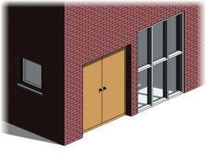
image © BIMscape
So let’s say that I want to pull the whole curtain wall panel out of the model to show the make-up and extent of it. This is where I would use Displacement Sets. But before I can do that I need to Lock my 3D View. Revit forces you to do this before you can create your Displacement Sets, to stop you inadvertently moving the View Point and messing up the relationship between the model and the displaced elements. So let’s lock the View using the tool on the View Control bar at the base of your view…
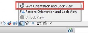
image © BIMscape
This has now locked your 3D View and you can no longer adjust it with the View Cube or Steering Wheels. So now we can create our Displacement Set. First of all select a mullion on the curtain wall (any mullion will do). Once you have selected a mullion (or indeed any other element in your model, in this view) you now have access to the Displace Elements tool…
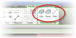
image © BIMscape
As soon as I click on this tool, two important things happen. Firstly the Ribbon changes to show me the tools that are associates with Displacement Sets. These are namely Edit, Reset and Path…
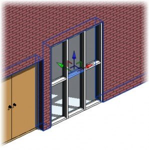
image © BIMscape
And secondly, the selected element (a mullion in this case) has a 3-axis movement control placed over it…

image © BIMscape
We can now simply grab one of these arrows with our cursor and drag the element in the corresponding direction. So to pull it away from the face of the building we need to use the Green arrow in our example. In the next image you will see how I have displaced the mullion away from the rest of the model…
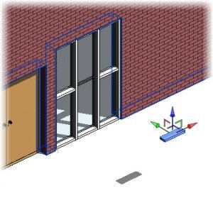
image © BIMscape
Now I could just repeat the above for each and every part that I wish to displace. But thankfully there is a much more efficient way of doing this. With our element still selected, I can click on the Edit button….
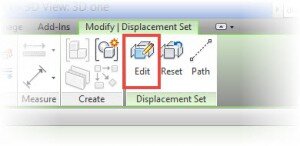
image © BIMscape
As soon as you do this, you will notice the whole view turns monochrome except for you selected element. You also get a floating menu panel which lets you add (and remove) elements to your displacement set…
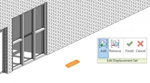
image © BIMscape
Now all you have to do is click on each element that you wish to add to your (already) displaced element and a Set is created. I am going to add all the other mullions and the curtain wall itself. Here is my completed Displacement Set….
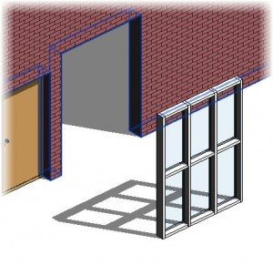
image © BIMscape
All that’s left for me to do is add my “path lines” in. These just help show where the element was displaced from. If you recall from earlier, Path was one of the menu options that became available once we chose to displace an element. So all I need to do is choose the Path tool…
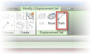
image © BIMscape
and now as soon as I hover over my my Displacement Set, Revit will find all the key points that it can create a Path to. Each time I click, a path line is created. Here is my final Displacement Set with 4 paths- one on each corner.
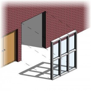
image © BIMscape
Just before we end this tutorial it is worth mentioning that Displacement Sets can be used on all model elements, but not 2D elements or Annotations.
This article was originally published on BIMscape and has been republished here with permission.
cover image © pexels